

Telecom
MIR performs cell-site audits and structural documentation on communication towers — capturing antenna azimuth, tilt, and RAD center, mount and cabling detail, and measurable digital twins for engineering, leasing, and close-out.

Blue UAS Cleared
Freefly Astro aircraft listed within the Blue UAS framework for procurement-sensitive missions.

$5M Aviation Liability
Coverage built for infrastructure field operations.
Redundant Aircraft
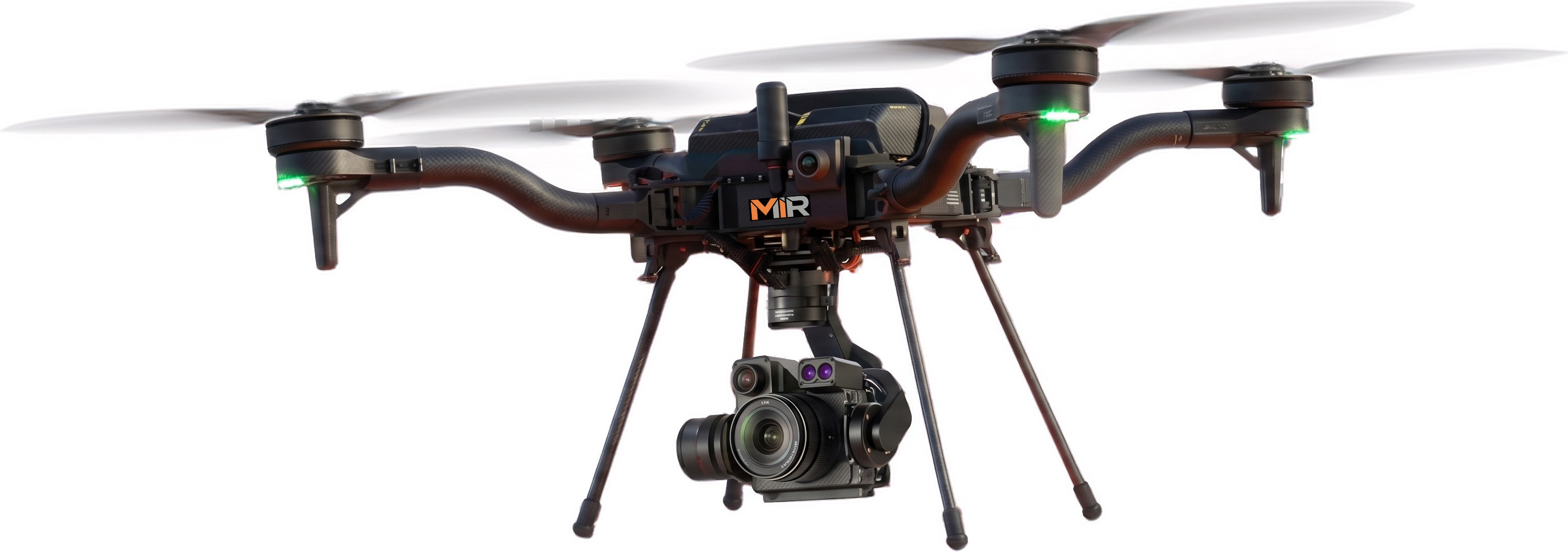
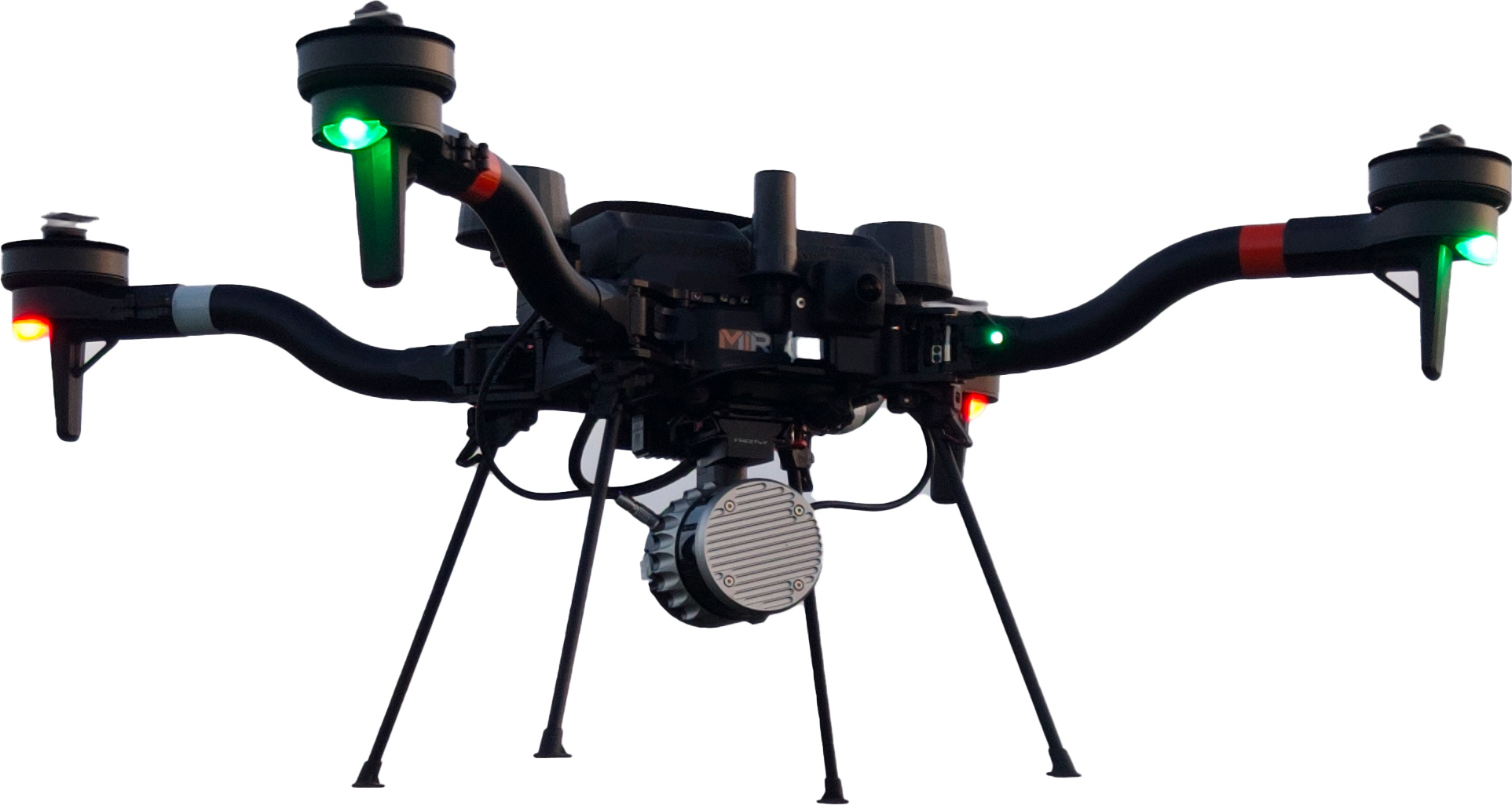
Dual American-made Freefly Astro platforms with RGB and LiDAR payloads for mission continuity.

Mobile Field Support
Charging, live viewing, and data review for sustained operations.
Communication tower structure and mounted equipment
Purpose-Built Data for Telecom
Climb crews are costly and constrained by weather and safety windows. MIR captures structured, high-resolution imagery and measurable 3D models of tower assets that support engineering review, colocation and mount-loading analysis, and carrier close-out packages. Findings are reviewed and severity-graded in Scopito with geo-tagged annotations and reviewer notes, producing audit-ready cell-site reports. The result reduces climbs, standardizes documentation across the portfolio, and gives engineering and leasing teams a consistent, dimensioned record of every site.
 Thermal
 RGB
RGB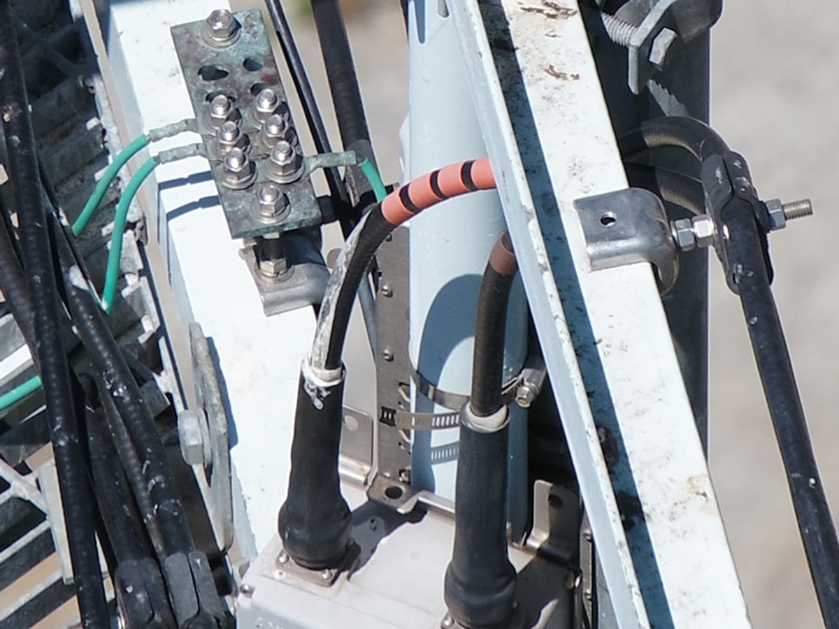 DetailOverview
High-Resolution Detail Inspection
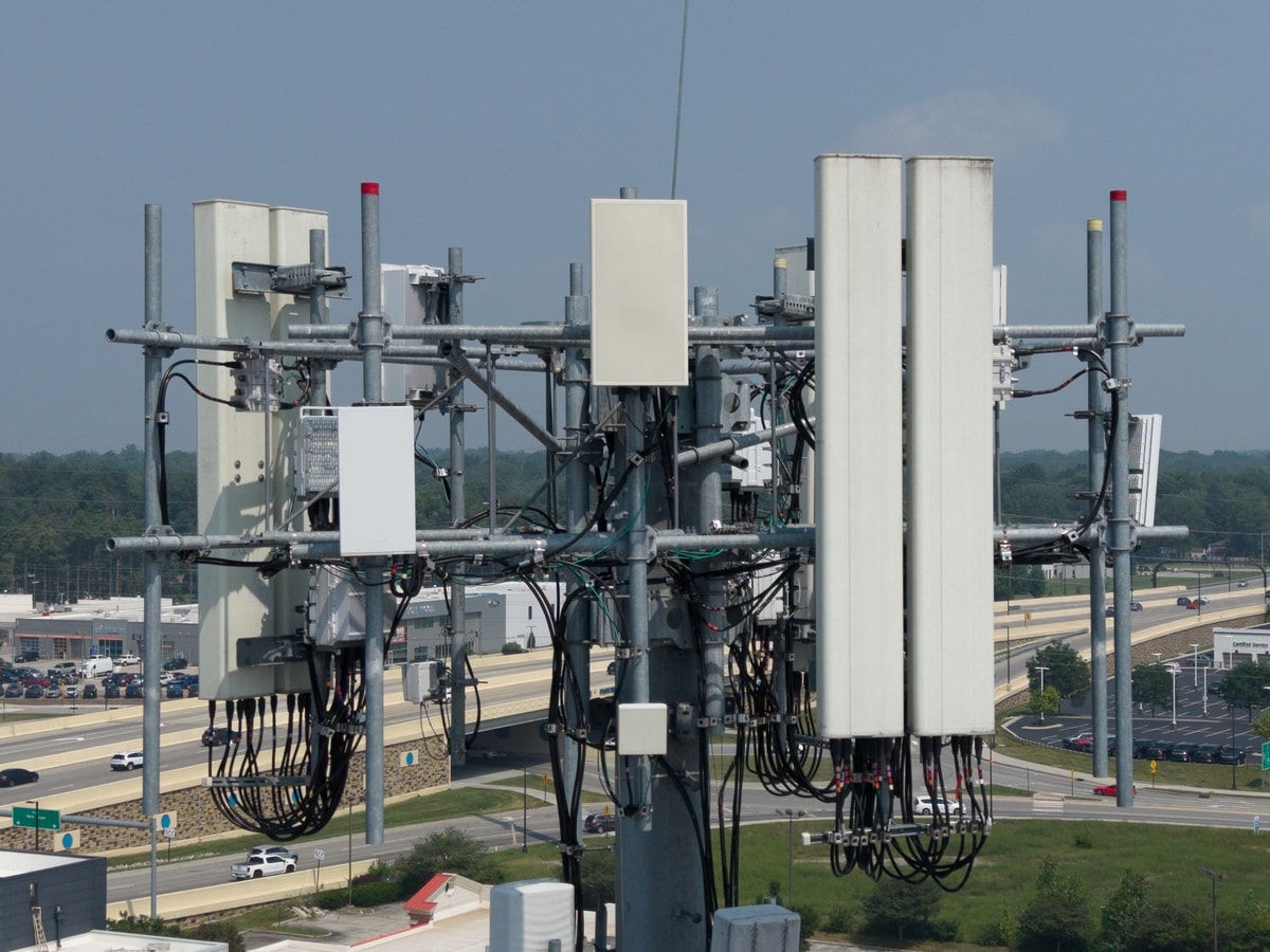
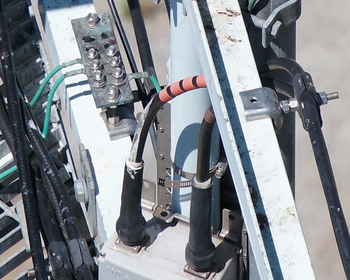
The same high-resolution imagery resolves down to the hardware. Drag from the full-site overview to a bolt-level detail crop — reading corrosion, grounding, weatherproofing, and connector condition without a climb.
From Flight Plan to Close-Out
Every telecom project runs the same repeatable pipeline: missions are planned in UgCS, flown autonomously by AMC (Auterion Mission Control) on American-made Freefly Astro aircraft, then offloaded to the right software — Pix4Dmatic for mapping and photogrammetry, Scopito for inspection findings, and Freefly Flow for in-field LiDAR point clouds.
- Step 01

Mission Planning
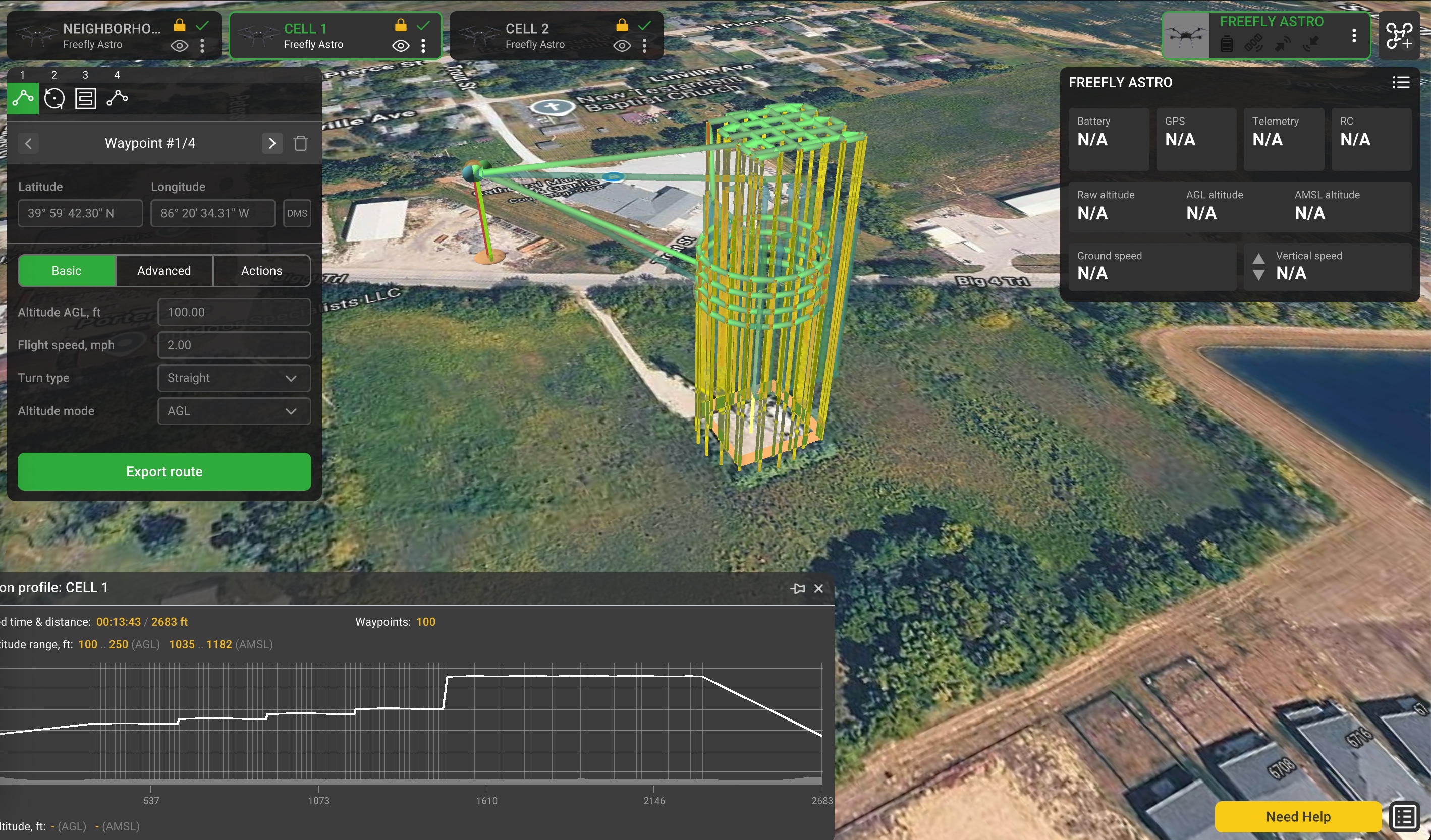
Towers are programmed in UgCS with circlegrammetry and vertical-scan paths at a fixed Ground Sampling Distance, capturing every face, mount, and appurtenance for a dimensionally accurate reconstruction.
- Step 02


Field Capture
The UgCS mission is transferred by USB to the Herelink controller and uploaded to AMC (Auterion Mission Control), which flies the repeatable, RTK-referenced circlegrammetry route autonomously on American-made Freefly Astro aircraft — capturing overlapping high-resolution imagery of the structure, antennas, mounts, and appurtenances. The same programmed mission can be re-flown on demand for consistent, comparable coverage.
- Step 03


Processing & Reporting
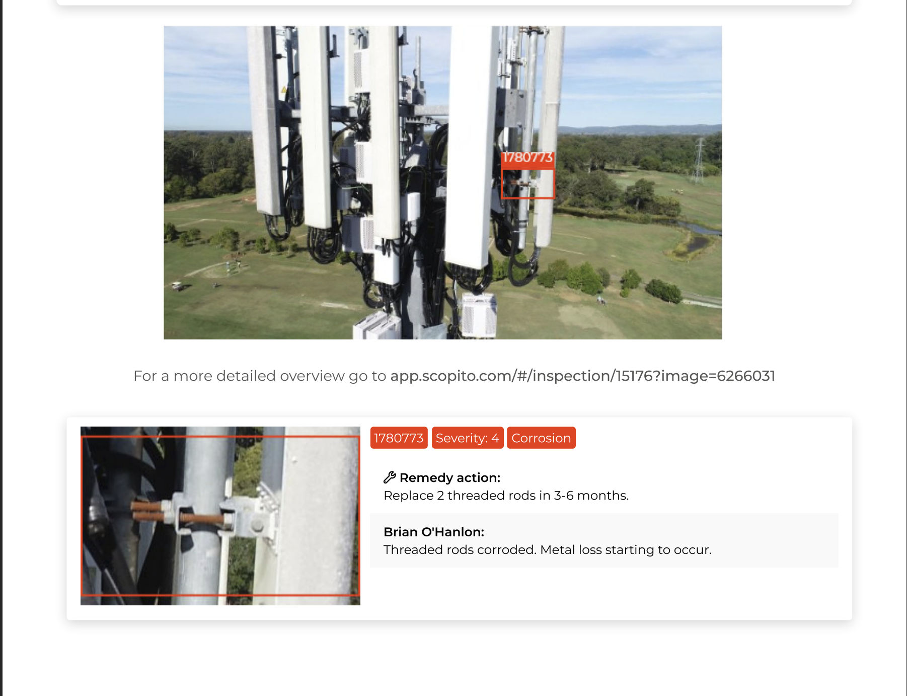
Imagery is reconstructed into a measurable digital twin in Pix4Dmatic, then reviewed in Scopito with geo-tagged, severity-graded annotations — producing cell-site audit reports, colocation exhibits, and close-out documentation.

Services MIR Provides
Tower Structural Inspection
Detailed imagery of members, welds, bolts, coatings, grounding, and lighting systems to support structural condition review.
Cell-Site Audit & Mount Documentation
Records of antenna azimuth, tilt, RAD center, mounting hardware, and cable routing to support audits, mount-loading, and change management.
3D Models & Digital Twins
Measurable 3D models and digital twins for remote review, colocation planning, and capacity analysis.
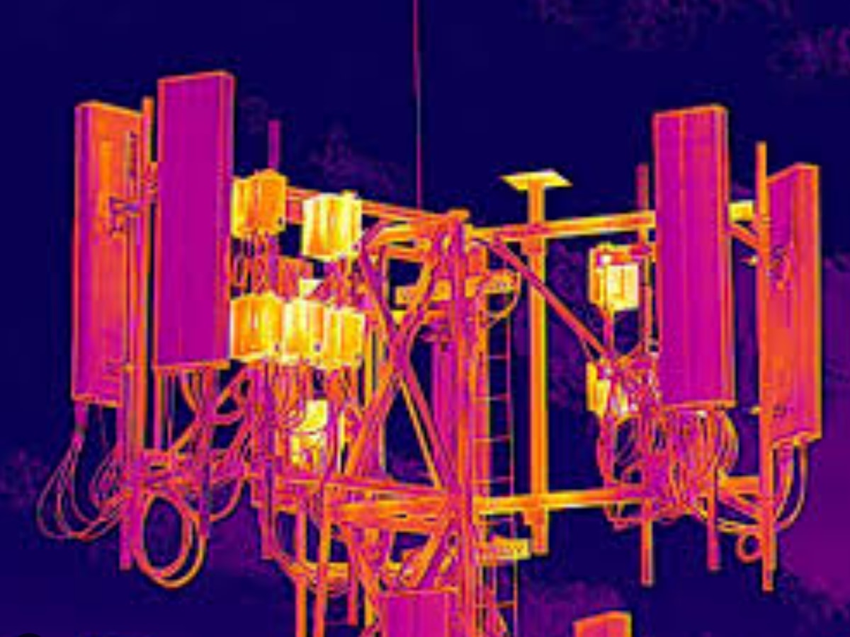
Radiometric Thermal Inspection
Thermal capture to identify heat anomalies at connections, radios, and equipment.
Colocation & Capacity Mapping
Measurement-ready data to evaluate available space, structural loading, and tenant planning scenarios.
Laser Rangefinder Measurement
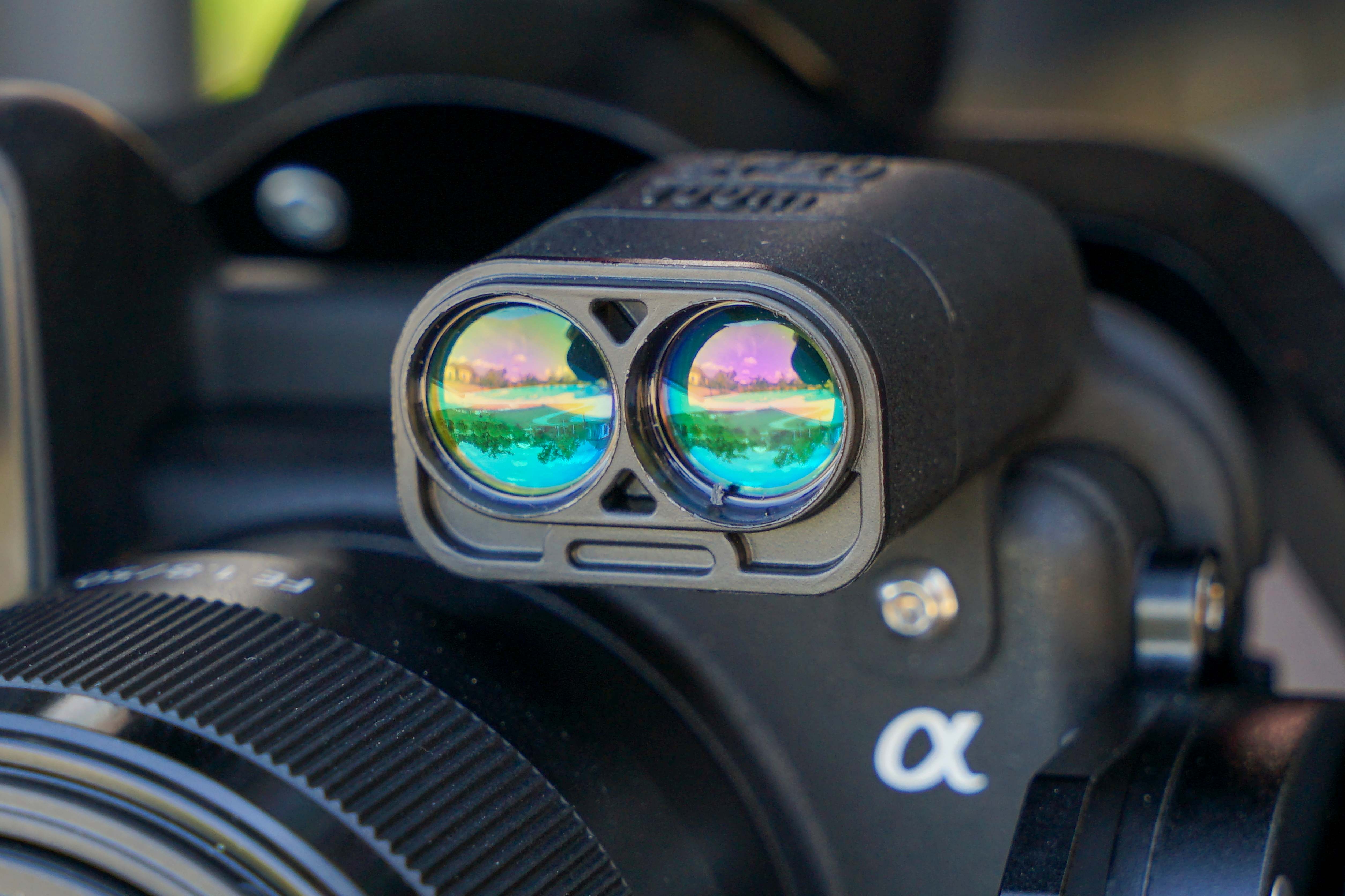
On-board laser rangefinder for precise height and clearance measurement — RAD center, antenna and appurtenance elevations, and mount offsets captured directly from the air without a climb.
The Equipment We Bring To Your Site
Each project is scoped to the required collection method. RGB, radiometric thermal, and LiDAR are deployed in purpose-built acquisition passes based on the required deliverables — RTK-referenced so your data comes back well-documented and ready to use.
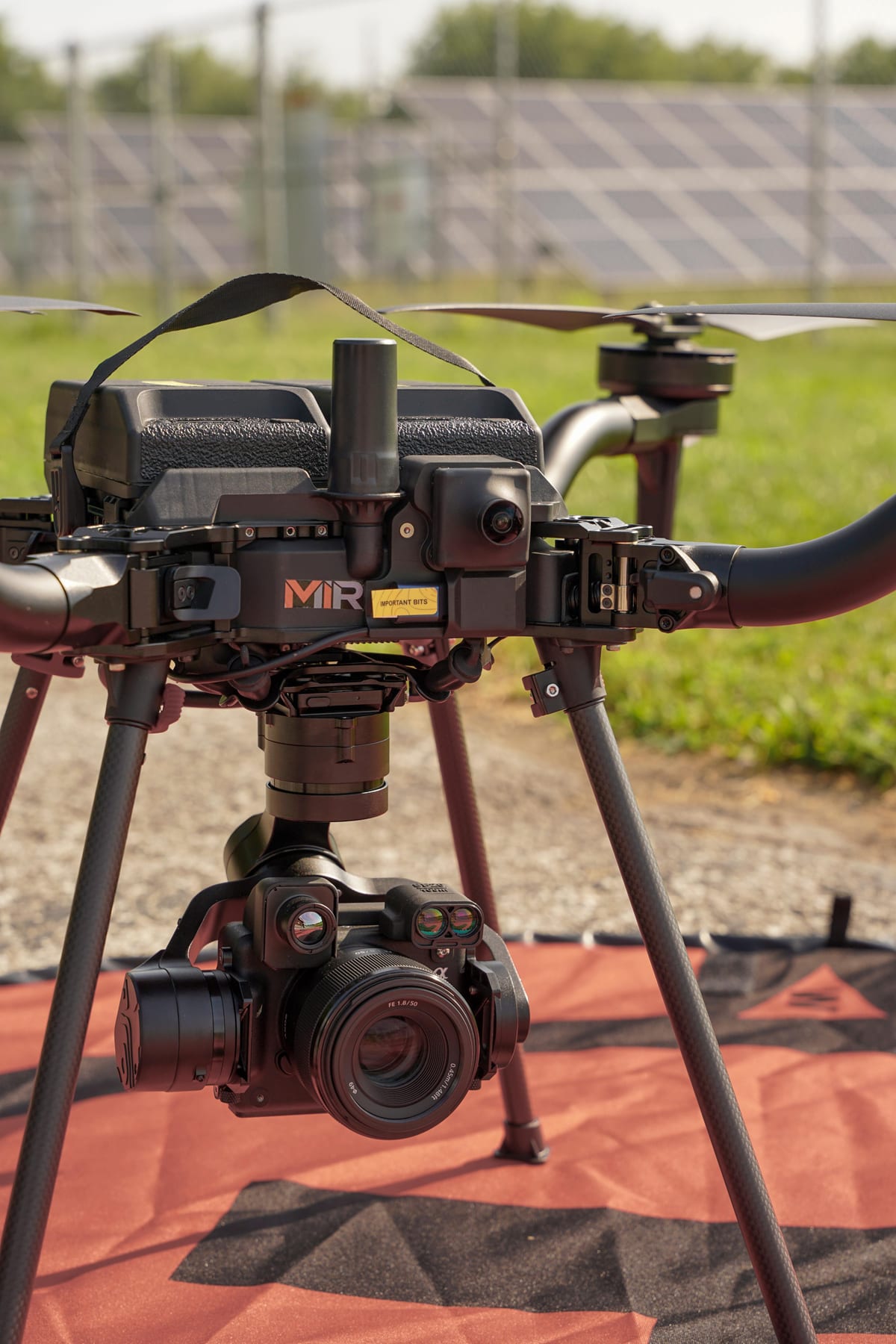
Freefly Astro
Blue UAS aircraft
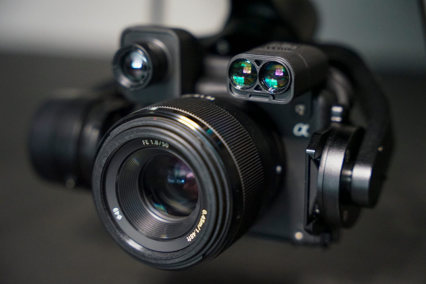
Sony 61MP RGB
High-resolution imagery
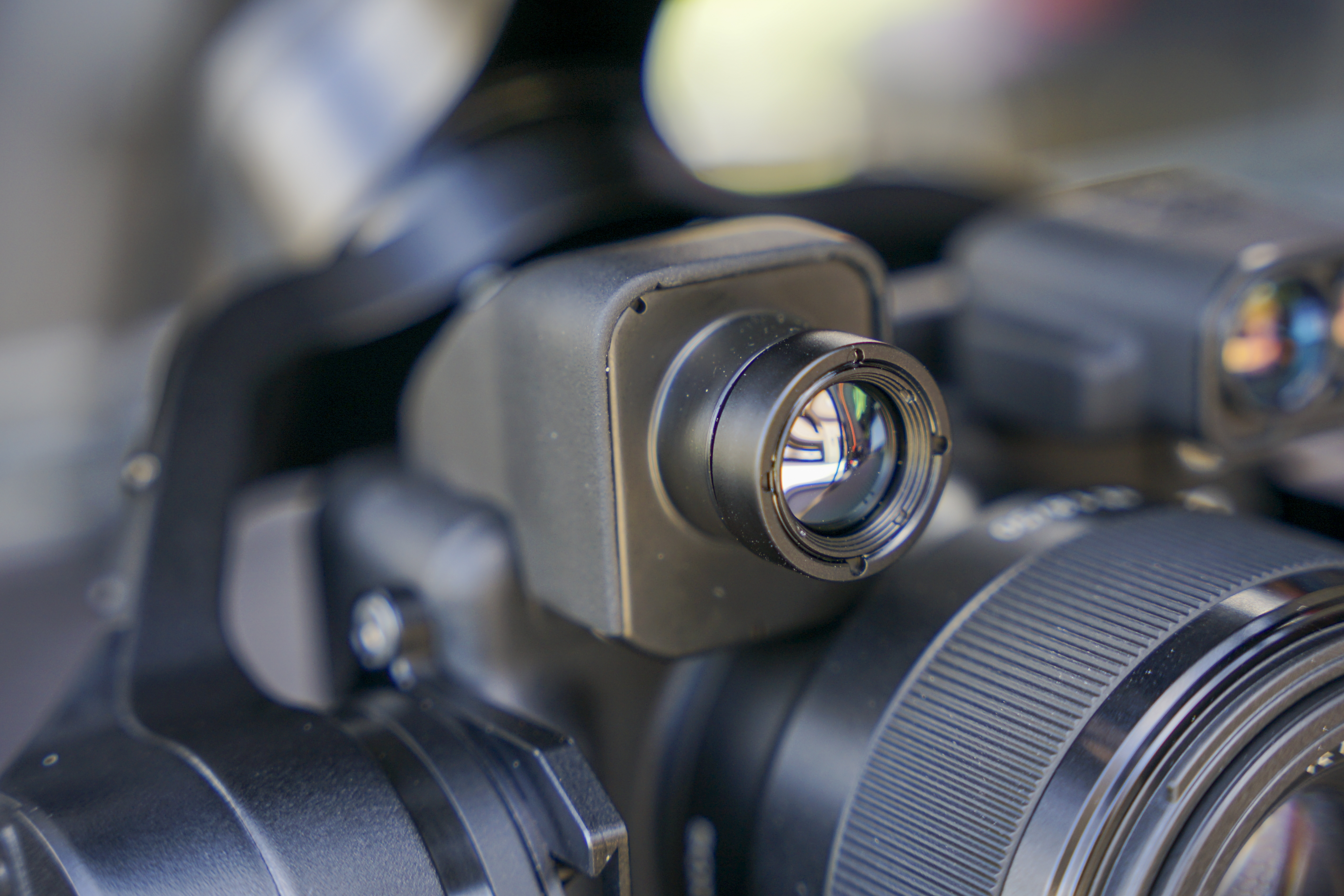
Radiometric Thermal
Calibrated heat mapping
Laser Rangefinder
Direct distance & clearance
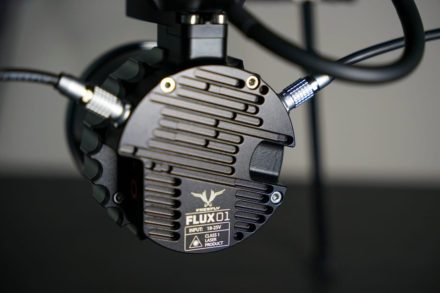
Freefly Flux O1
LiDAR acquisition
RTK Positioning
InCORS NTRIP · WGS 84
One cell-site audit, one file
Azimuth, tilt, and RAD center documented for every antenna, findings severity-graded, and the whole audit packaged for your engineering and leasing teams to act on.
Cell-site audit
Azimuth, tilt, and RAD center captured for every antenna and mount.
Measurable digital twin
3D models for remote review, colocation, and mount-loading analysis.
Severity grading
Geo-tagged findings graded in Scopito with reviewer notes.
Report Sample
Inside a Scopito Cell-Tower Report
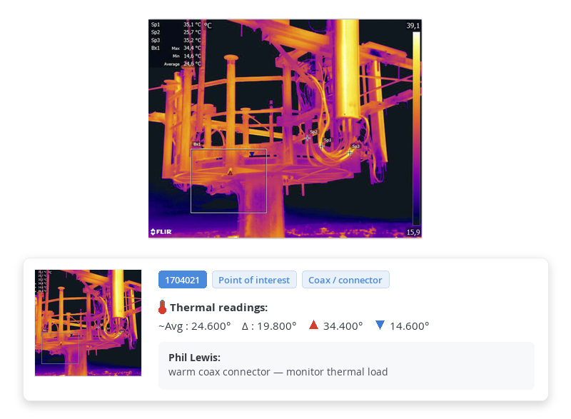 Thermal
Thermal · Coax Connector
Platform coax connector — elevated temperature flagged
- Avg
- 24.60°
- Max
- 34.40°
- Δ Delta
- 19.80°
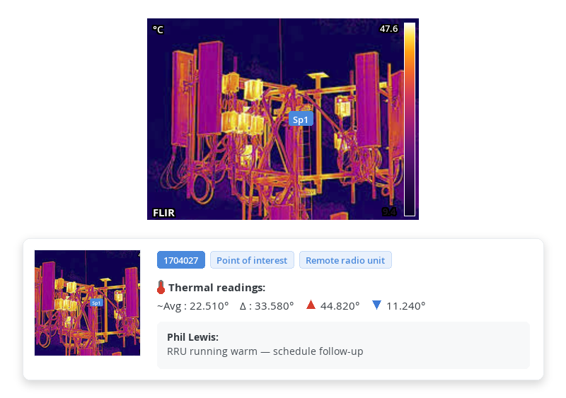 Thermal
Thermal · Remote Radio Unit
Remote radio unit running warm — follow-up scheduled
- Avg
- 22.51°
- Max
- 44.82°
- Δ Delta
- 33.58°
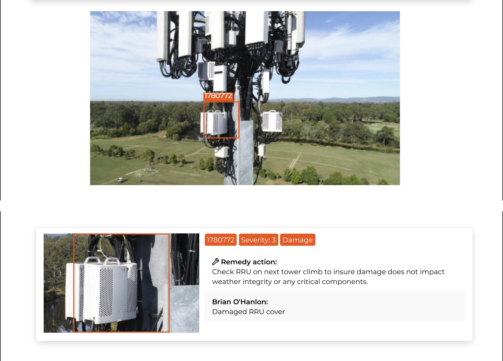 Sev 3 · Damage
Damaged RRU cover flagged with a remedy action
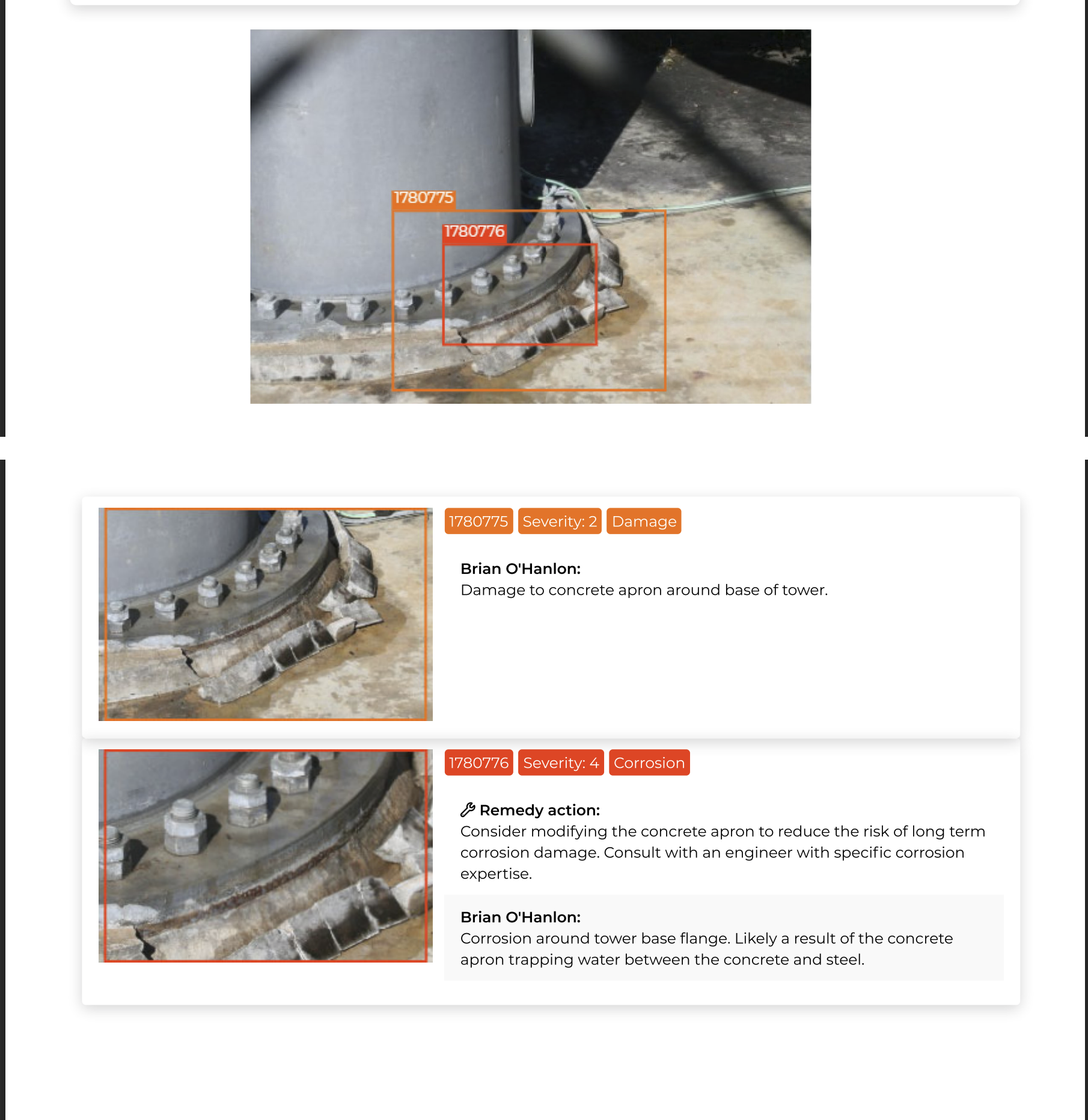 Sev 4 · Corrosion
Base-flange corrosion from a water-trapping concrete apron
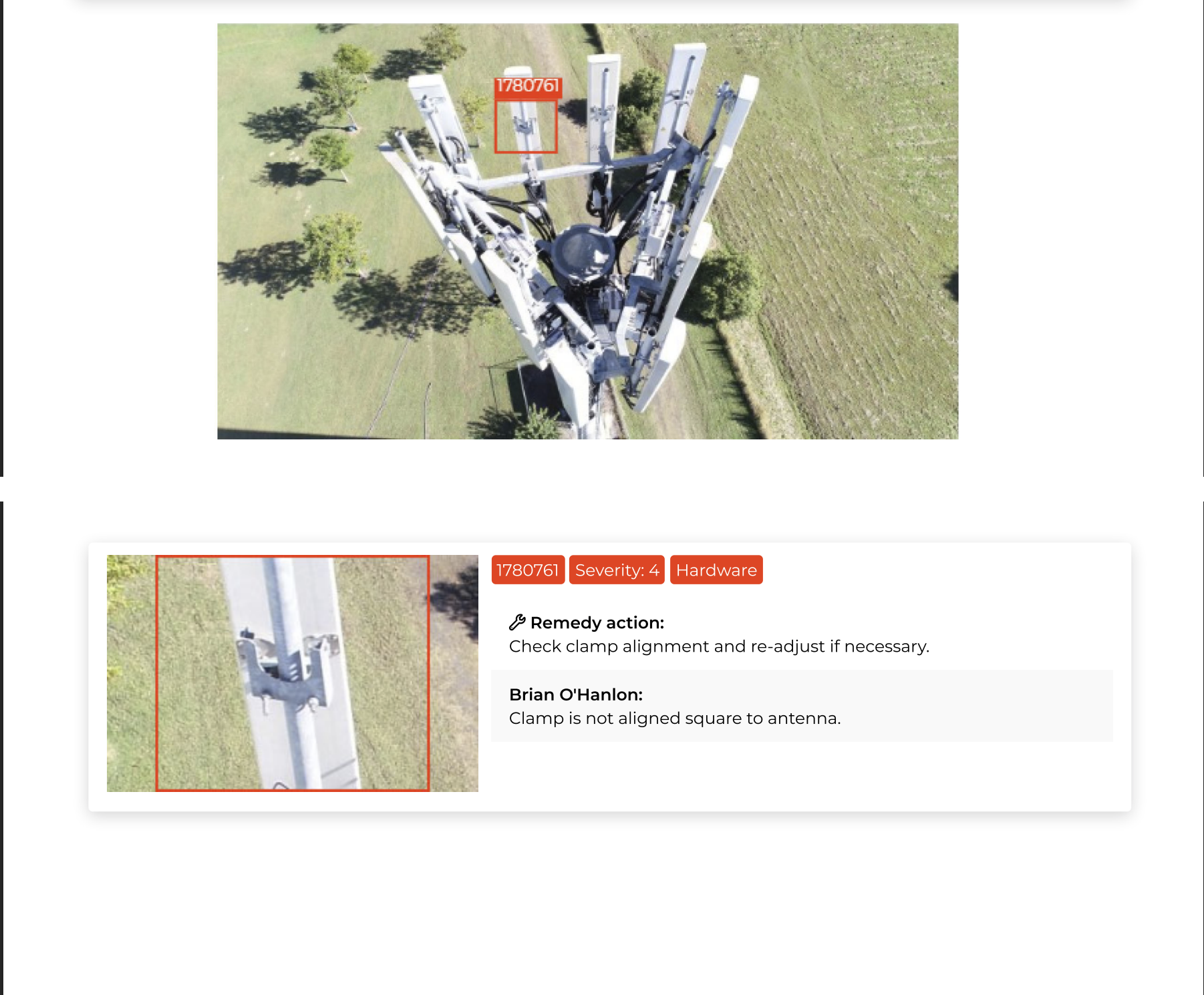 Sev 4 · Hardware
Mount clamp out of square — flagged for re-adjustment
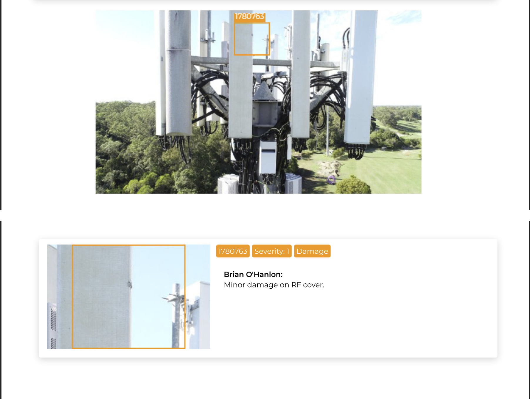 Sev 1 · Damage
Minor RF-cover damage logged for monitoring
Want a sample report for your fleet?
Blue UAS Cleared aircraft · American-made platform · mobile field deployment
Explore Other Industries MIR Serves
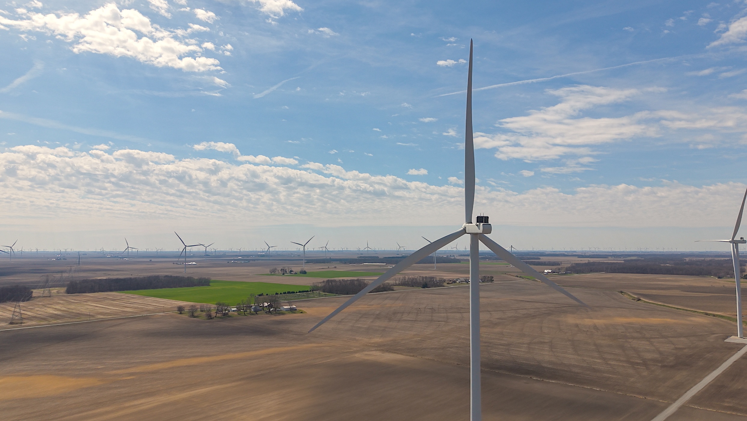
Wind Energy
Wind inspection data collection and vendor support — blade, tower, and nacelle records that pinpoint leading-edge erosion and serial defects without prolonged downtime.
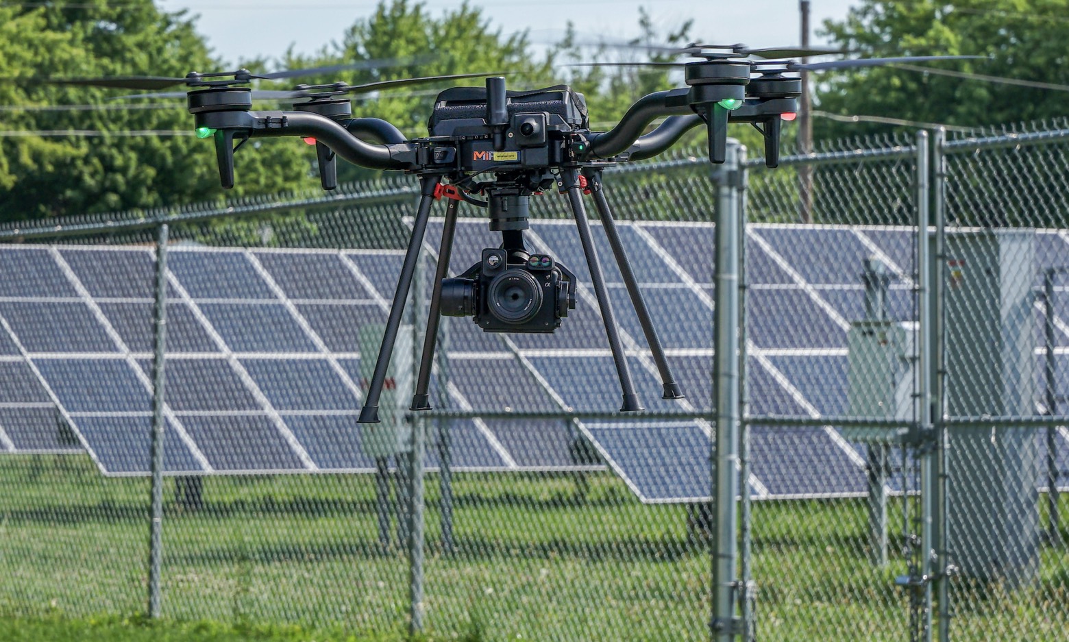
Solar & Renewables
Aerial thermography that locates hot spots, diode failures, and string outages down to the module.
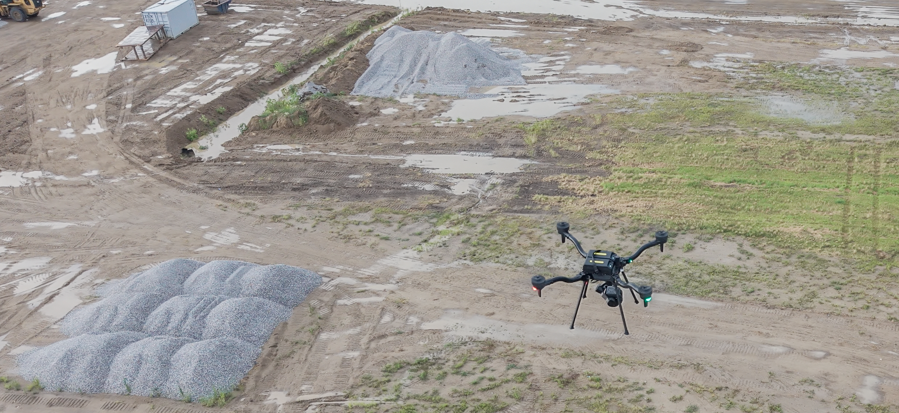
Mining & Aggregates
RTK-referenced stockpile volumetrics, pit-progression models, and highwall documentation — captured with high-accuracy photogrammetry and LiDAR, without entering hazardous zones.
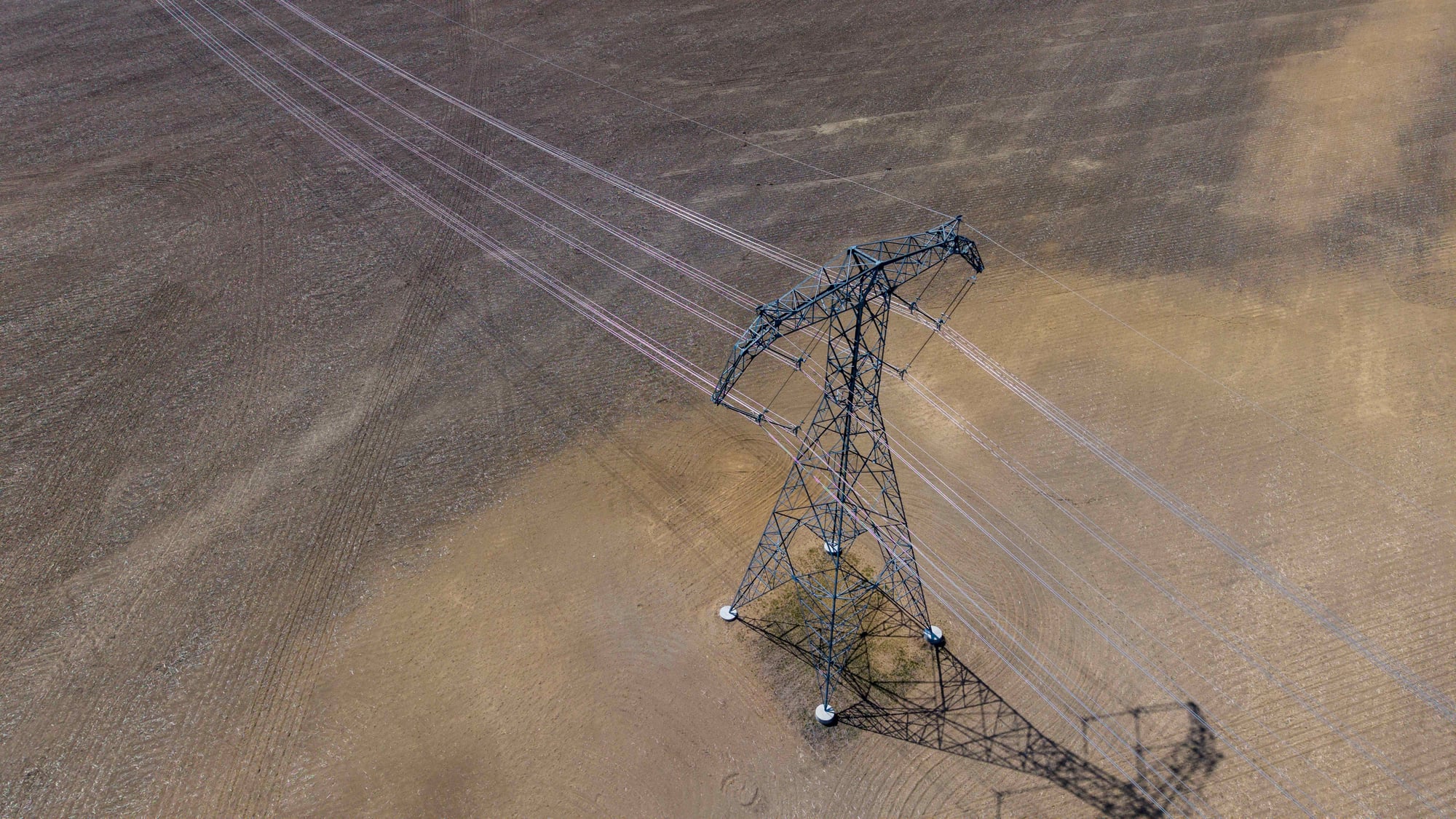
Utilities & ROW
T&D structure inspection, LiDAR corridor mapping, and vegetation-encroachment documentation for reliability and compliance.
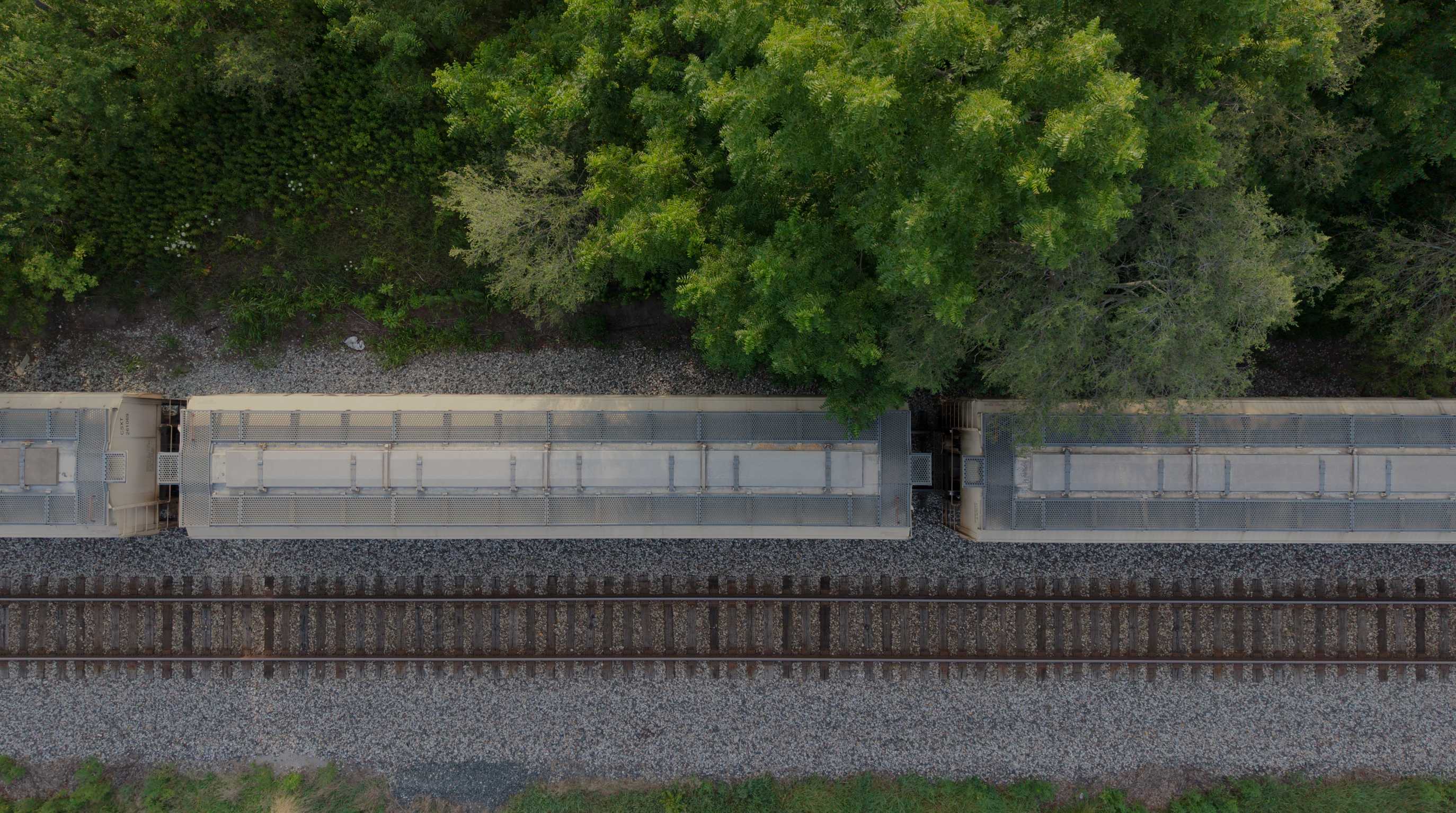
Rail & Transportation
RGB corridor mapping and LiDAR data along rail corridors — reducing time spent on or near live track.
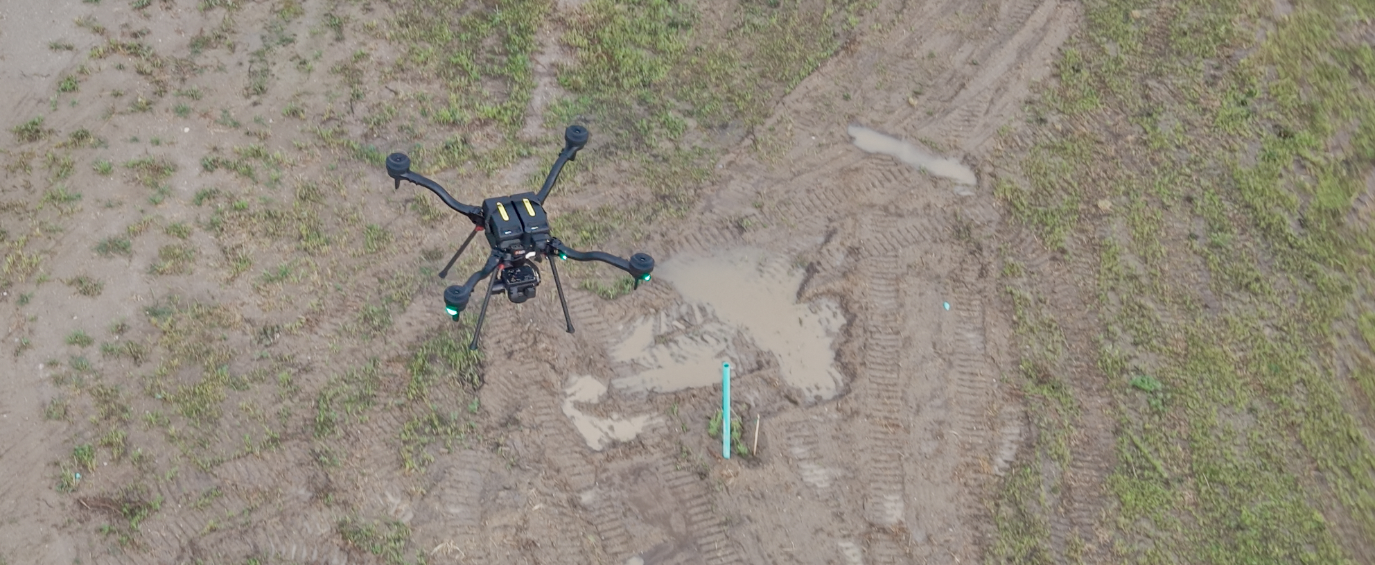
Civil & Geospatial Support
RTK-enabled aerial LiDAR and 61MP RGB collection — orthomosaics, point clouds, terrain surfaces, and construction documentation to support licensed survey teams, civil engineers, developers, and contractors.
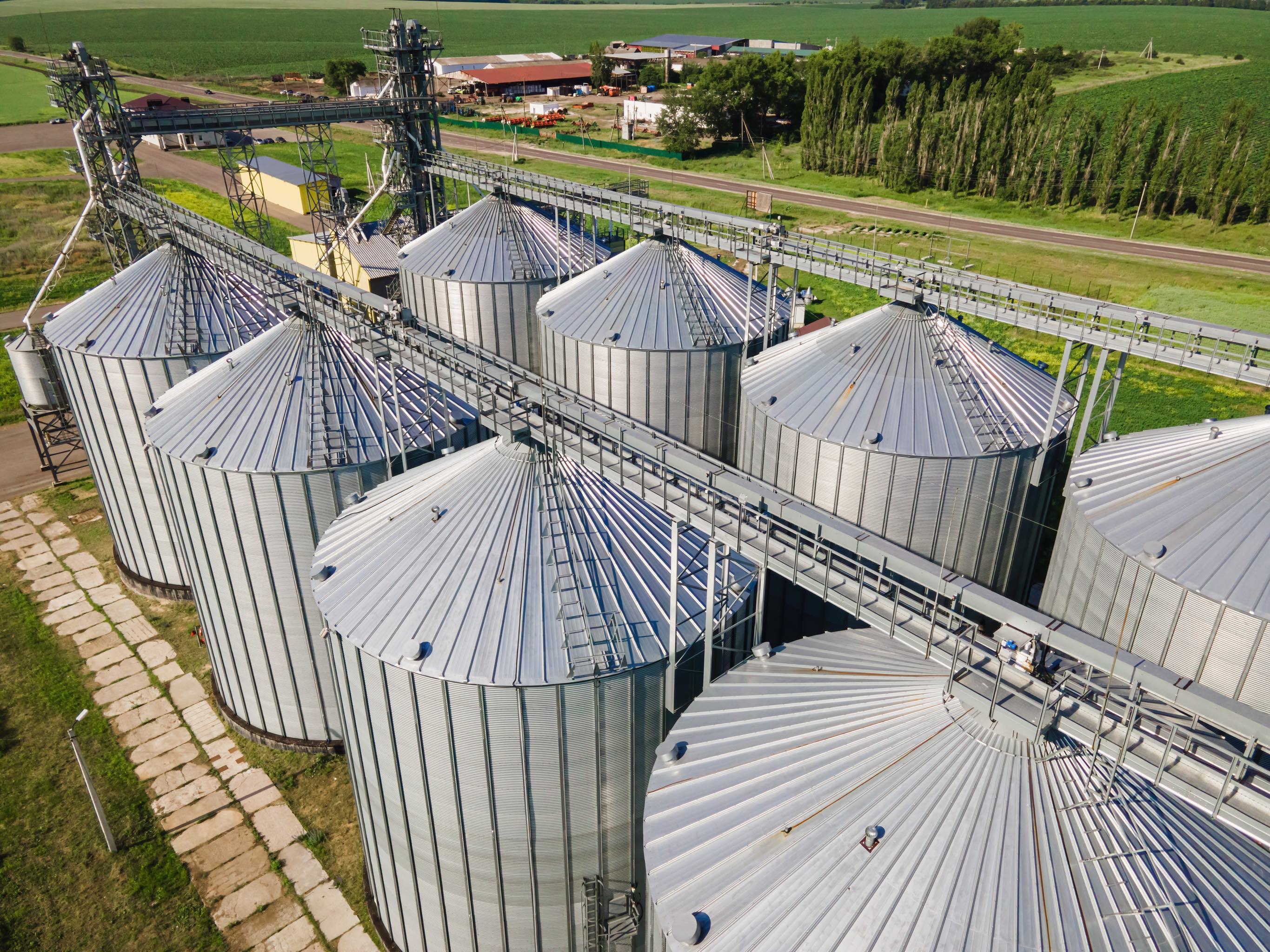
Grain Storage & Handling
Exterior condition documentation, thermal risk screening, and RTK-referenced quantity data for concrete silos, steel grain bins, elevator structures, handling equipment, and visible open storage.
Start With the Project Objective
Have a Telecom Project?
Tell us what needs to be inspected, mapped, measured, or documented. We'll help determine the right collection method, payload, mission structure, and deliverables.